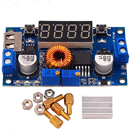
XL4015 5A Step Down Module with Digital Voltmeter
The module comes equipped with a voltmeter, ammeter, power meter, and a USB interface for charging digital products.
A buck converter or step-down converter is a DC-to-DC converter that steps down voltage (while stepping up current) from its input (supply) to its output (load). It is a class of switched-mode power supply. This product is a 180 KHz fixed frequency PWM buck (step-down) DC/DC module, capable of driving a 5A load with high efficiency, low ripple, and excellent line and load regulation. The module with a voltage meter to display the input voltage and output voltage, and the voltage can be corrected through the button to improve the accuracy of the voltmeter.
Note:
• When you use the product, the module inputs and outputs must be isolated from the ground.
• USB output voltage is consistent with the module and NOT a fixed 5V output. When charging digital equipment, make sure the USB output voltage is 5V.
• When you encounter a scenario where the module cannot adjust the output voltage and it is always equal to the input voltage, turn the voltage potentiometer counterclockwise 10 times or more, following which you can adjust the output voltage. The factory default output voltage is set to 20V.
Specification:
DANGER WARNING!!! Please note that the USB port is not for charging phones. If you set the unit to 12V output and plug in your phone on the USB side it will damage your phone.
• Input voltage range: 5-36VDC
• Output voltage range: 1.25-32VDC adjustable
• Output current: 0-5A
• Output power: 75W
• High efficiency of up to 96%
• Built-in thermal shutdown function
• Built-in current limit function
• Built-in output short protection function
• Input reverse polarity protection: None (if required, the high current diode in series with the input).
• Size: L x W x H =68.2×38.8×15mm
Application:
1. Use as step-down modules with overcurrent protection
• Adjust the right button so that the “OUT” LED is lit, the Digital meter shows the value of output voltage, and adjust the “voltage potentiometer” so that the output voltage reaches the value you want.
• Adjust the right button so that the Digital meter shows the value of the output current; Wire shorted output terminal, then adjust the “current potentiometer” so that the output current reaches a predetermined overcurrent protection value. (For example, the Digital meter displays the current value of 4A, then you can use the module to a maximum current of 4A)
• Connect to the load.
2. Use as a battery charger
• Make sure you know the battery float voltage and charging current; (if lithium parameters 3.7V/2200mAh, then the float voltage is 4.2V, the maximum charging current 1C, i.e. 2200mA)
• Under no-load conditions, adjust the “Voltage potentiometer” so that the output voltage reaches the float voltage; (if to 3.7V rechargeable lithium battery, the output voltage can be adjusted to 4.2V)
• Adjust the right button so that the Digital meter shows the value of the output current; Wire shorted output terminal, then adjust the “current potentiometer” so that the output current reaches a predetermined Charging current value.
• Charge turn lamp current factory default is 0.1 times the charging current; (Battery during charging current is gradually reduced, if the charge current setting is 1A, then when the charge current is less than 0.1A, blue lights turned off, the green light is on, which means that the battery is fully charged)
• connect to use as a battery charger
• (1,2,3,4 step as Output is unloaded, do not connect the battery)
3. Use as a LED constant current driver module
• Adjust the “voltage potentiometer” so that the output voltage reaches the value you want.
• Adjust the right button so that the Digital meter shows the value of the output current; Wire shorted output terminal, then adjust the “current potentiometer” so that the output current reaches a predetermined LED operating current.
• Connect LED.
• (1,2 steps as Output is unloaded, do not connect LED)
Voltmeter and ammeter calibration method:
Module with manual calibration function can correct display precision voltage and current, if you think the current voltage and current are accurate do not perform the following operations.
1. Output voltage calibration steps
• Step 1, adjust the right button so that the “OUT” LED is lit, Digital meter shows the value of output voltage; Press the right button for more than 2 seconds, release, Digital meter and “OUT” LED flashes in synchronization so that you enter the output voltage calibration mode.
• Step 2, press the right button (normal speed), the voltage value is adding up a unit; Press the left button, minus a unit; Due to a unit being less than 0.1V, the minimum voltage display to 0.1V, so you need to continuously press 1-5 times to see the voltmeter change 0.1V, how many times voltmeter change 0.1V by pressing the key, depending on the current display voltage, the higher the voltage, the fewer the number of press.
• Step 3, press the right button for more than 2 seconds, and release, to exit the output voltage calibration mode. All parameters are set to automatically power down to save.
2. Input voltage calibration steps
• Step 1, adjust the right button so that the “IN” LED is lit, Digital meter shows the value of input voltage; press the right button for more than 2 seconds, release, Digital meter and “IN” LED flashes in synchronization so that you enter the input voltage calibration mode.
• Steps 2 and 3, are consistent with the output voltage calibration method.
3. Output current calibration steps
• Step 1, adjust the right button so that the Digital meter shows the value of output Current. Press the right button for more than 2 seconds, and release, Digital meter flashes in synchronization so that you enter the output current calibration mode.
• Step 2, Connected to the load, and ammeter in series, adjust the right and left buttons to change the display of the digital meter, so that is consistent with the ammeter display.