WZ5012L Bench Power Module
Item highlights:
1.1 LCD can display input/output voltage, output current/output power/output capacity/output time;
1.2. Voltage can be adjusted on the pot accurately and fast.
The output voltage can be adjusted from 0-48V with a input power source of no more than 45V max, and the current can be adjusted from 0-12A.
1.3. The output is protected against voltage feedback
1.4. The output voltage can be switched on or off by means of pressing the button.
1.5. Multiple software protection mechanisms are available, and the protection threshold is adjustable. When the working parameters of the module exceed the protection threshold, the output will automatically be switched off.
1.6. Using synchronous rectification technology, the conversion efficiency is high: the efficiency is more than 90%.
1.7. The heatsink and the fan will help with heat dissipation.
Product parameters
|
model: WZ5012L |
display: LCD |
|
Input voltage range: 6-48.00V |
Input voltage resolution: 0.01V |
|
Output voltage range: 0-48.00V |
Output voltage resolution: 0.01V |
|
Output current range: 0-12.00A |
Output current resolution: 0.01A |
|
Output power range: 0-600W |
Input voltage accuracy: ±(1%+5) |
|
Output voltage accuracy: ±(0.3%+5) |
Output current accuracy: ±(0.5%+5) |
|
Typical value of output ripple: 150mV Peak value |
Normal operating temperature range: -10℃~40℃ |
|
Capacity measurement range: 0-999.9AH |
Statistical error of capacity energy: ±2% |
|
Statistical time range: 0-100 hour |
Depressurization mode: differential pressure >0.05%+1V |
|
The weight of the node: 200g Including packing: 242g |
Product size: panel 79X43X42mm main board: 106x76x40mm |
Soft start: Yes
Protection mechanism:
Input under voltage protection is available by adjusting setting parameters (5.8-45v adjustable, default 5.8v)
Output overvoltage protection is available by adjusting setting parameters (0-50.00v adjustable, default 50V)
Output over-current protection is available by adjusting setting parameters (0-12.00A adjustable, default 12.00A)
Timeout protection is available by adjusting setting parameters (0 - 100h adjustable, off by default)
Overcapacity protection is available by adjusting setting parameters (0 – 999.9ah adjustable, off by default)

3. Key description


Note: after the product triggers the protection mechanism, the output will automatically turn off, the LCD will display the protection code, and pressing any key will exit the protection interface
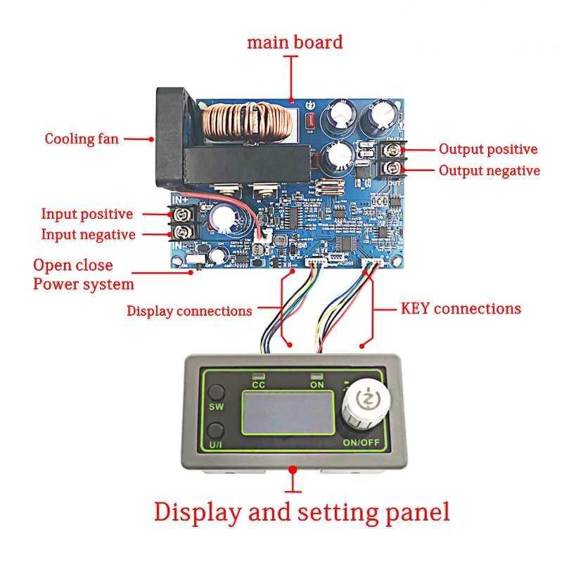
4. Interface description

Method of use
Switch display parameters -- in the normal interface, press SW to switch the display below the display screen, and switch the display content between current A and power W capacity Ah time h. Long press the SW button to switch the uplink display on the display screen and switch the display content between input voltage IN and output voltage OUT.
Set output voltage -- press the U/I button in the normal interface to enter the interface of setting voltage constant current. It can be seen that a certain digit of the output voltage value is flashing. Rotate the encoder left and right to adjust the major and minor. Short press the rotary encoder to choose which bit of output voltage to set. After setting, press the U/I button 2 times to return to the normal interface. Or automatically return to the normal interface after stopping operation for 10s.
Set constant current value (that is, the maximum current value allowed to output by the module) -- press the U/I button in the normal interface to enter the setting voltage constant current interface. Then press the U/I button and switch to set the constant current value. You can see a bit of the setting constant current value flashing. Rotate the rotary encoder left and right to adjust the major and minor. Short press the rotary encoder to choose which bit to set the constant current value. After setting, press U/I to exit the setting voltage constant current interface and return to the normal interface. Or automatically return to the normal interface after stopping operation for 10s.
Set the default on/off state of module power-on -- long-press U/I in the normal interface to enter the parameter setting interface. You can see that it shows "OPEN OFF" or "OPEN ON". "OPEN OFF" means the output is turned OFF by default when power is ON, and "OPEN ON" means the output is turned ON by default when power is ON. The long-press rotates the encoder to switch two states. After setting, long press U/I to return to the normal interface.
Setting of protection parameters on state and threshold -- long-press U/I to enter the parameter setting interface in the normal interface. Press SW until the protection you want appears. LUP -- under-voltage protection threshold; OUP -- overvoltage protection threshold; OCP -- overcurrent protection threshold; OAP -- ultra-capacity protection threshold; OHP timeout protection threshold. Short press rotates the encoder to select which bit you want to set the protection parameter to. Long press the rotary encoder to set the protection parameters on or off (only timeout protection and super capacity protection can be set to turn on/off, and other protection parameters are turned on by default). Rotate the encoder left and right to make the parameters bigger and smaller. After setting, long press U/I to return to the normal interface.
Calibration voltage and current -- press the U/I button to enter the parameter settings interface under the normal interface. Press the SW key for a short time until the interface with zero appears, with zero + out + a symbol. Press and hold the rotary encoder to complete zero calibration. Short press the SW button until a parameter interface with CAL appears. The calibration input voltage interface should appear with the symbols CAL + IN + V; The calibration output voltage interface should appear with the symbols CAL + OUT + V; The calibration output current interface should appear with the symbols CAL + OUT + A. Rotate the encoder left and right to adjust the size of the parameters. After the adjustment is completed, long-press the rotary encoder to confirm the adjustment is completed, after the parameter value is no longer flashing. Long press U/I to return to the normal interface.
Note: In order to ensure the accuracy of calibration, and calibration voltage - start calibration only when the voltage is above 12V; Calibration current - start calibration only when the current is above 1A.
Caution
The module input positive in + and negative in - must not be reversed, and the module input in - must not be short-circuited with the output out -, otherwise the module can be damaged.
Please ensure that the input current of the power supply exceeds the required output current!
This module is a step-down module, the input voltage should be higher than the output voltage, and a certain margin should be reserved. For full load output, the input voltage shouldn't be higher than max 50V will not work at this high voltage for long period of time.
When using the module at high Current levels it could cause serious heating, be careful of hot surfaces! Please pay attention to ventilation and heat dissipation when using high currents for a long time!
The module has an input under-voltage protection function. The default value is about 5.8v (which can be adjusted). When the value is lower than the set value, the output will automatically be disconnected.