GY-30 Light Intensity Illumination Sensor BH1750FVI
DESCRIPTION:
The BHI1750FVI is a digital ambient light intensity sensor with I2C interface and output directly readable in Lux.
PACKAGE INCLUDES:
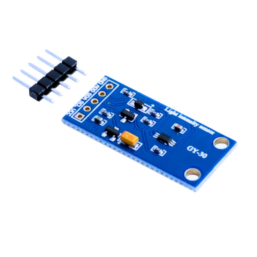
- GY-30 BH1750FVI Digital Ambient Light Intensity Sensor Module
- 6-pin male header
KEY FEATURES OF GY-30 BH175-FVI DIGITAL AMBIENT LIGHT INTENSITY SENSOR MODULE:
- Visible light sensitivity with peak at 560nm
- 1 – 65535lx measurement range
- ± 45 degree angle of sensitivity to 50%
- 50/60Hz light noise rejection
- Compatible with most white light sources
- ± 20% measurement variation
- I2C interface with readout in Lux
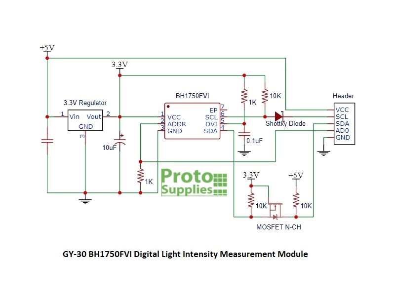
- On-board 3.3V regulator and logic level translators
- 3.3 and 5V compatible
The BH1750FVI sensor was designed to add ambient light sensing to LCD displays in cars, cameras, mobile phones and similar equipment. For automatically controlling the backlight dimming of the displays. The fact that the output is directly readable in Lux (lx) makes it useful in a number of light-sensing applications.
The sensor is designed to detect the light spectrum visible to the human eye with peak sensitivity at 560nm which is in the green spectrum. The full range spans approximately 400nm to 700nm.
The sensor works well with most white visible light including the sun, incandescent, fluorescent, halogen and white LED lighting. It has good UV and IR rejection.
The GY-30 module incorporates a 3.3V regulator and can be powered from either 3.3V or 5V.
The I2C has logic level shifting circuitry to make the module compatible with both 3.3V and 5V logic. The SDA pin uses a MOSFET for level translation since it is a bi-directional signal. the SCL pin uses a diode / resistor to level shift since it is uni-directional.
The Address line has a 1K pull-down resistor on the module so that the I2C address defaults to 0x23 if the pin is left unconnected. If the address line is pulled HIGH, the address is 0x5C.
Module Connections
The module brings out the following connections.
1 x 5 Header
- GND = Ground
- AD0 = Address. Default is pulled LOW = 0x23. HIGH = 0x5C
- SDA = I2C Data
- SCL = I2C Clock
- VCC = Power (3.3V or 5V)
Module Assembly
The module ships with the male header strip loose. The header can be soldered to the top or bottom of the module depending on the planned use or wires can be used to make the connections.
For breadboard use, we put the headers on the bottom. Soldering is easiest if the header is inserted into a breadboard to hold it in position during the soldering process.
What we found when working with the sensors:
These are nice assemblies and very easy to use.
The range on this sensor is very wide and can differentiate between subtle differences in brightness.
Measurement accuracy is stated as ± 20%. When compared to a Lux meter the readings from the BH1750FVI were typically 10-20% higher and very repeatable. For most applications absolute values are not too important, but it would be easy to add an offset to the measurement if a reference Lux meter is available to calibrate the reading to.
The program below uses the library from Rob Tillaart that can be installed from the Arduino IDE library manager. It is a simple program that reads the output of the sensor every second and prints reading in Lux to the Serial Monitor window.
For connections, simply connect the VCC to 5V or 3.3V and GND to ground. Connect SDA pin to SDA on the MCU and SCL pin to SCL on the MCU
BH1750FVI Digital Ambient Light Intensity Sensor Module Test Program
TECHNICAL SPECIFICATIONS
| Operating Ratings | ||
| Vcc Range | Typical | 3.3 – 5V |
| Measurement Variation | Typical | ±20% |
| Spectral Detection | Detection Range | 400nm-700nm |
| Peak Detection | 560nm | |
| Angle of Half Sensitivity | ± 45° | |
| Dimensions | L x W (PCB) | 33 x 15mm (1.3 x 0.59″) |
| Datasheet | ROHM | BH1750FVI |
