L9110S H-bridge
Internal Reference:
MOD-054
L9110S H-bridge.
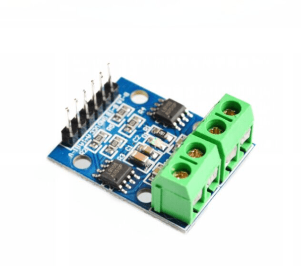
This L9110S Dual-Channel H-Bridge Motor Driver is a compact motor driver chip that supports a voltage range from 2.5-12V at 800mA of continuous current. These chips have built-in output clamp diodes to protect your sensitive microcontroller electronics. They are suitable for very small robot projects.
A very compact dual-channel H-bridge motor driver module. The module incorporates two L9110S H-bridge driver ICs to allow either one stepper or two DC motors to be independently controlled. The module can accept a supply voltage between 2.5 to 12V allowing for motors within this supply. Perfect to be used with An Arduino and robot chassis.
L9110S H-bridge Pins Explanation:
- VCC and Ground. Connect the VCC and GND pins to a battery pack or similar to drive the motors, that way you do not get the power from your Arduino board, protecting it from overcurrent.
- A-IA: Control the forward movement of motor A
- A-IB: Control the backward movement of motor A
- B-IA: Control the forward movement of motor B
- B-IB: Control the backward movement of motor B
Below is a sketch to get you going. Connect the h-bridge to the PWM pins on your Arduino. To quickly explain the code the sketch has 4 functions called forward(), backward(), left() and right(). I added another one called stop() to make it more complete.
This sketch also comes with a speed variable that you can change if the bot moves too fast, currently, it is set to 255 which might be too fast,
The first 4 lines of code in the sketch show you the pin hook up to your Arduino. From here on it is relatively easy, if you have an IR remote for example you can assign each of the keys to the different motor functions for example:
if (irrecv.decode(&results)) {
if (results.value=="XXXX"){ //XXXX represents the remote forward button code
forward();
}
irrecv.resume(); //wait for the next signal
}
The library includes lots of code examples, in particular, look for this one example called IRrecord. You can use that one as is to view the remote controller's key codes. You can for example then replace the XXXX of the forward button with your remote's forward button code in your sketch.
Do the same for the backward, left, right, and stop remote control buttons and you have a working robot operated by a remote controller!
PDF DOCUMENT: L9110_2_CHANNEL_MOTOR_DRIVER
L9110S H-bridge Sketch:
const int AIA = 9;  // (pwm) pin 9 connected to pin A-IA
const int AIB = 5;  // (pwm) pin 5 connected to pin A-IB
const int BIA = 10; // (pwm) pin 10 connected to pin B-IA
const int BIB = 6;  // (pwm) pin 6 connected to pin B-IB

byte speed = 255;  // change this (0-255) to control the speed of the motors

void setup() {
  pinMode(AIA, OUTPUT); // set pins to output
  pinMode(AIB, OUTPUT);
  pinMode(BIA, OUTPUT);
  pinMode(BIB, OUTPUT);
}

void loop() {
  forward();
  delay(1000);
  backward();
  delay(1000);
  left();
  delay(1000);
  right();
  delay(1000);
  stop();
  delay(1000);
}

void backward()
{
  analogWrite(AIA, 0);
  analogWrite(AIB, speed);
  analogWrite(BIA, 0);
  analogWrite(BIB, speed);
}

void forward()
{
  analogWrite(AIA, speed);
  analogWrite(AIB, 0);
  analogWrite(BIA, speed);
  analogWrite(BIB, 0);
}

void left()
{
  analogWrite(AIA, speed);
  analogWrite(AIB, 0);
  analogWrite(BIA, 0);
  analogWrite(BIB, speed);
}

void right()
{
  analogWrite(AIA, 0);
  analogWrite(AIB, speed);
  analogWrite(BIA, speed);
  analogWrite(BIB, 0);
}
void stop()
{
  analogWrite(AIA, 0);
  analogWrite(AIB, 0);
  analogWrite(BIA, 0);
  analogWrite(BIB, 0);
}