4N35 Transistor Output Optocoupler, Through Hole, 6-Pin PDIP
This product is no longer available.
Internal Reference:
EC-168
.
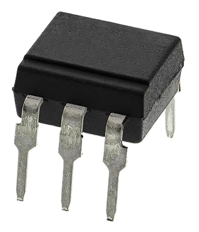
4N35 Transistor Output Optocoupler, Through Hole, 6-Pin PDIP
4N35 contains an IRED optically coupled to a photo transistor. It is packaged in a 6pin DIP, available in wide-lead spacing option and SMD. Input-output isolation voltage (rms) is 5.0kV. Collector-emitter voltage is 80V(*) and CTR is 50% to 600% at input current of 5mA. It can be used with Arduino.
4N35 is commonly used for isolating the micro controller unit from external source, load and sensors as protection and Signal transmission between circuits of different potentials and impedance.
Specifications
This section mentions some of the important features and specifications of the optocoupler IC.
- Number of Channels: 1 Channel
- Maximum Collector-Emitter Voltage: 30V
- Forward Current: 100mA
- Forward Voltage: 1.5V
- Reverse Voltage: 6V
- Isolation Voltage: 5300 Vrms
- Operating Temperature: -55 to 100 Degree C
- Power dissipation: 250 mW
Features :
- 6pin DIP package
- Double transfer mold package (Ideal for Flow Soldering)
- High collector-emitter voltage (VCEO:80V(*))
- Current transfer ratio (CTR : MIN. 50% at IF=5 mA, VCE=5V)
- High isolation voltage between input and output (Viso (rms) : 5.0 kV)
Working of the Optocoupler IC
The optocoupler IC consists of gallium arsenide infrared LED and a silicon NPN phototransistor and using the IC is also pretty easy. To use the IC as a phototransistor we will not be needing the base pin(pin 6). The working circuit below can be followed to design your own circuit and get the optocoupler IC to use.

The infrared LEDs anode(pin1) and cathode(pin 2) pins are to be connected to the logic input and the ground, respectively. The collector pin(pin 5) is pulled up using a resistor and the output device is connected to the other end. Here for our case, we have connected an output probe to monitor the output. The emitter pin(pin 4) is to be grounded.
Note: Do not connect the emitter and the cathode pin to the same ground as they are meant to be isolated.
Working: When the IR LED is provided with a logic 0 input the LED will be in OFF condition and will not trigger the transistor and the output we will receive is a HIGH across the collector-emitter terminal. Whereas, when the LED is provided with a logic 1, LED will turn on and trigger the transistor and shorts the collector-emitter junction and we will receive a 0 at the output.
Note: The Collector-emitter voltage can be set up to a maximum of 30V.
Alternatives
MCT2E, PC817, 6N137
Applications
Here are some of the applications of the EL4N35 optocoupler IC.
- Relay driving circuits
- Switch-mode power supply feedback
- AC mains detection
- Logic ground isolation
Resources
Here is the 4N35 Datasheet if you require any additional information