3.5 inch SPI TFT Module
Internal Reference:
DL-048
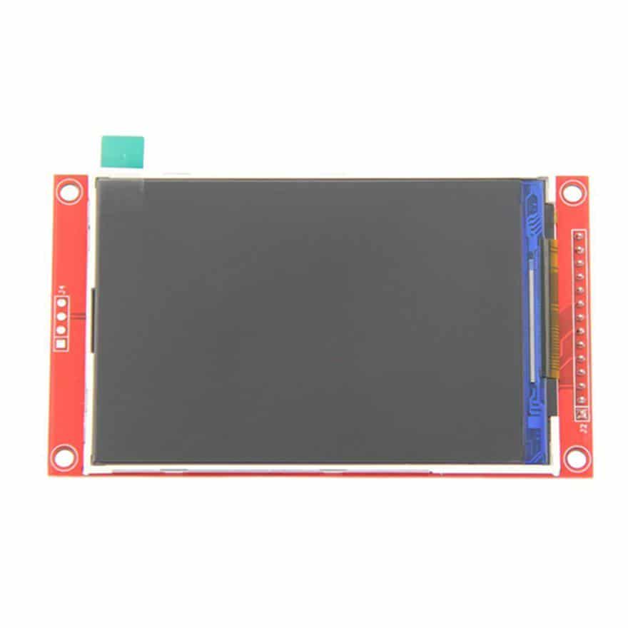
The 3.5-inch TFT LCD with SPI Interface is an exceptional display for your ambitious projects. This screen also features an SD card slot, which conveniently stores the images you wish to showcase.
3.5-inch TFT LCD with SPI Interface Specifications:
- Display Color: RGB 65K colour
- Screen Size: 3.5(inch)
- Type: TFT
- Driver IC: ILI9488
- Resolution: 480*320 (Pixel)
- Module Interface: 4-wire SPI interface
- Active Area (AA area): 48.96x73.44(mm)
- Module PCB Size: 56.34x98(mm)
- Operating Temperature: -20℃~60℃
- Storage Temperature: -30℃~70℃
- VCC power voltage: 3.3V~5V
- Logic IO port voltage: 3.3V(TTL)
- Power Consumption: TBD
- Rough Weight: 45 (g)
Note*
When we directly connected the SPI display module without the on-board level conversion module to the Arduino, we found that it could not run at all. This is because the SPI module's pin can only input a 3.3V high level, while the Arduino output has a high level of 5V. To run successfully, there are two Method: short circuit method and external level conversion module method. The short-circuit method has the advantages of simple operation, short wiring, and no need for external devices. The disadvantage is that the module generates a large amount of heat during operation. Will affect the life of the module. The external level conversion module method is a normal operation, and the advantage is that the module generates less heat and runs stably during operation, and the disadvantage is that the operation is slightly complicated. (An external level shifting module is required) to increase the cost (additional level conversion module is required). In summary, it is recommended to use the external level shifting module method.
Step 1: Short-Circuit Method
The short-circuit method is to short the J1 component position (shown below) with solder on the back of the module. After shorting, the runtime module VCC The pin must be connected to a 5V power supply (not connected to 3.3V).
Step 2: External Level Conversion Module Method
The so-called external level conversion module method is to connect the Arduino and the display module through an external level conversion module, so that The 5V high level of the Arduino output is converted to 3.3V by the level conversion module and then input to the display module. As shown below:
The ILI9488 TFT lib. look at link: GitHub link
Pinout:

|
Number |
Pin Label |
Description |
|
1 |
VCC |
5V/3.3V power input |
|
2 |
GND |
Ground |
|
3 |
CS |
LCD chip select signal, low level enable |
|
4 |
RESET |
LCD reset signal, low level reset |
|
5 |
DC/RS |
LCD register / data selection signal, high level: register, low level: data |
|
6 |
SDI(MOSI) |
SPI bus write data signal |
|
7 |
SCK |
SPI bus clock signal |
|
8 |
LED |
Backlight control, high level lighting, if not controlled, connect 3.3V always bright |
|
9 |
SDO(MISO) |
SPI bus read data signal, if you do not need to the read function, you cannot connect it |
|
(The following is the touch screen signal line wiring, if you do not need to touch function or the module itself does not have touch function, you can not connect them) |
||
|
10 |
T_CLK |
Touch SPI bus clock signal |
|
11 |
T_CS |
Touch screen chip select signal, low level enable |
|
12 |
T_DIN |
Touch SPI bus input |
|
13 |
T_DO |
Touch SPI bus output |
|
14 |
T_IRQ |
Touch screen interrupt signal, low level when touch is detected |