Water Level Controller project
This step-by-step project will control the fluid level in water reservoirs. It will allow the reservoir to drain to a specific point then turn on a pump or solenoid valve to refill the tank to a set point.
Difficulty rating: Intermediate
Average time to build: 45 minutes.
Quick description
This home automation project will control the water level in tanks. It works by monitoring the liquid levels in a tank and turning on/off a pump or solenoid valve as needed to maintain the water level within set parameters.
Steps
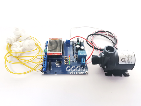
1. Install the components: This includes attaching and wiring together your water level sensor, control circuitry, pump or solenoid valve, power supply, etc
The current level will also be shown on our Bot Shop App. The app has an override button for the pump if you want to fill the tank outside of the normal operation.
No more guessing the level of your JoJo tank you can see the water level right from your phone.
Water level controller building summary
To be able to build this project all you need is 3 float switches, 6 resistors, a pump, and our Project Board.

A float switch contains a magnetic switch (reed switch) with a magnet that is able to float when the magnet rises with the water it activates the reed switch which we are then able to read with a microcontroller and make decisions accordingly.
Step-by-step instructions.
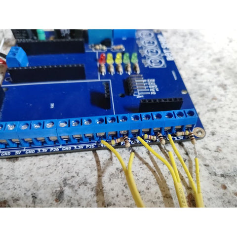
Step 1.
Connect a 4.7kOhm (yellow-purple-red-gold) resistor between 3.3v and P34. Connect one end of a 100Ohm (brown-black-brown-gold) to P34 and the other end to one end of the float switch. connect the other end of the float switch to GND. This will be the lower-level switch. Repeat this with P35 (middle-level switch) and P32 (upper-level switch).
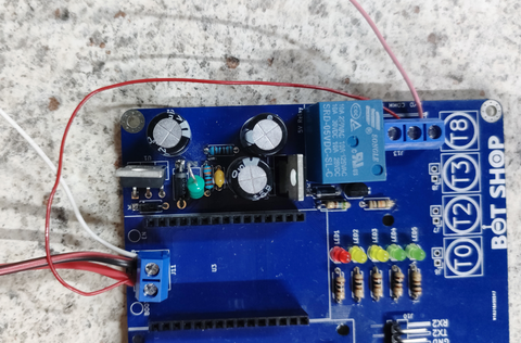
Step 2. B
Connect the positive of your pump to the N/O Pin of the relay and the negative of your pump to the negative of your voltage input. Next, add a jumper from the positive voltage input to the COMM pin of the relay. Please note that this configuration is only valid when the input voltage matches the voltage of the pump. If you are running a 220V pump follow Step 2. B.
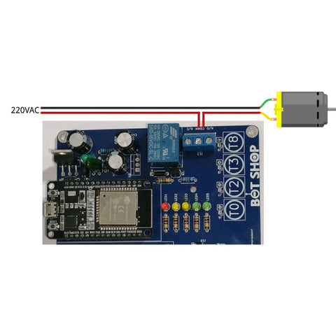
Step 2. B
If you are using a 220V pump follow this step instead of Step 2.A. Connect live and neutral to your pump as usual with a 3-prong plug at the other end but do not plug it in yet. Take the live wire and cut it so that you have 2 parts as if are adding a switch. Connect one end to the COMM Pin of the relay and the other end to the N/O Pin of the relay.
Step 3
Plug in your ESP32 to its socket and upload the code found at the bottom.
Code example!
Water Level Controller