Uni Sensor PCB Kit
The kit teaches you how the 358 Op-Amp IC can be used to get a sensor value compared to a set value and then switch a relay ON or OFF. You can use many different sensors with this kit.
Difficulty rating: Beginner
Average time to build: 30 minutes
This DIY kit will help with your soldering skills, while you learn about the standard 358 Op-Amp IC.
It intergrades a voltage-follower NPN transistor and Zenner as a stable voltage regulator.
So, you can power it with a wide voltage range without worrying about the variable set voltage stability of the sensor or pot values.
Quick description
This universal sensor board can be set up as a daylight switch or Temp switch
by only using an LDR or NTC as our sensor for the application this will switch a Relay on at a set value selected using a pot.
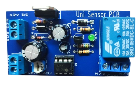
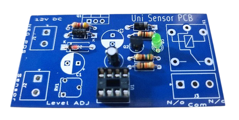
Uni Sensor PCB
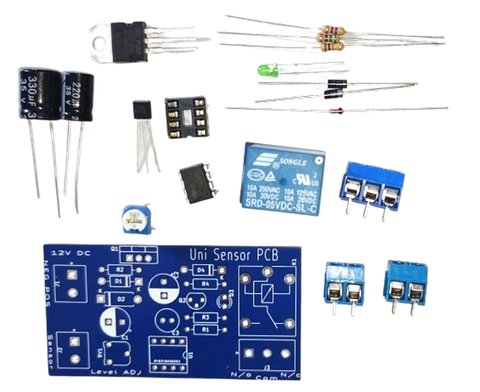
In this project, you will need the kit as well as a soldering iron, solder and pliers to cut the legs of the components shorter once completed.
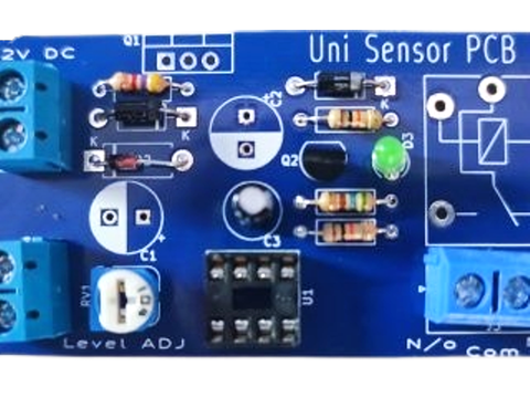
Product diagram
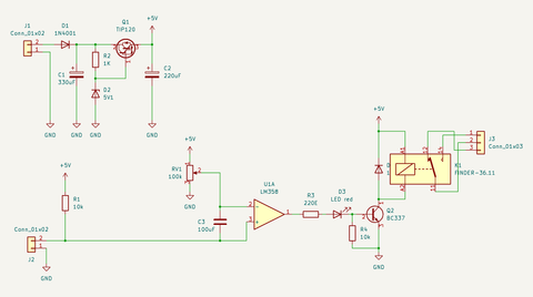
This shows how the sensors use LM358 IC. LM358 is a low-cost good quality dual operational amplifier IC that is used as a comparator in the circuit.The circuit is a dark sensor; that will show visual indications by activating an LED and Relay,
The working of the circuit is simple, when the photoresistor or LDR receives light, it will switch on the transistor BC337(NPN), when the transistor becomes ON it will activate the relay switch and any equipment connected with the relay will become activated. The relay value should be used according to the operating voltage. It is also important to always check how many amperes your relay can handle and how many amperes your appliance will use. Let's say your appliance's working ampere is 8 and you are using a 10-ampere relay then it will run smoothly but if your appliance current consumption is up to 10A then you have to use a higher current handling relay switch. The ampere of the relay and operating voltage are always written on the relay.
Step-by-step instructions
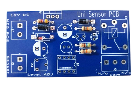
Step 1:
Place all Resistors, Diode, Zenner and solder pins (always start with the lowest components, this will make soldering easy when flipping PCB when soldering bottom.) Please ensure that the polarity of the diodes is correct, simple way of knowing is, the line on the diode needs to be in the same direction as the squared bracket line on the board.
Step 2:
Place the IC holder, transistor, and LED and make sure of the direction and polarity
(this will be the next highest level of components)
Step 3:
Place 2way and 3way blue connectors, the 10K pot (this will be the next highest level of components)

Step 4:
Place the Relay electrolytic caps and ensure polarity and direction as they have markings and are sensitive to reverse polarity and may burn out if not correct.
Step 5:
Select your sensor and set the pot at the level for the relay to switch.
Uni Sensor PCB