Sun following solar panel tutorial.
Hi there, today we will be learning how to create a solar panel that follows the sun using Arduino. This project is quite customizable and along the way will teach you how to use LDR's, Servo motors and coding in the Arduino IDE.
This is my first Arduino project?
If this is your first Arduino project or you need a little more insight on the components you're working with, here are a few useful links to get you started:
- Downloading and getting started with Arduino IDE
- What are Libraries?
- How to add Libraries to Arduino IDE
- Servo Motors with Arduino
- LDR's with Arduino
Software requirements
For this project you'll need to add the Servo library in your Arduino IDE. Simply go to Sketch>Include Library> Manage Libraries. When the window opens search for the ''servo'' library and install the first one that pops up.
- Arduino IDE
- Servo.h Library
Hardware requirements
There are a few components needed for this project to work which I will add links to :
- Wrapping Wire
- Breadboard
- Male to Male Jumper wires
- LDR x2
- 10k Resistors x2
- Mini Nano USB cable
- Arduino Nano
- Sg90 Servo Motor
The hardware in the list above can all be bought from our website here.
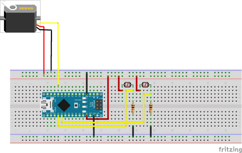
Circuit diagram
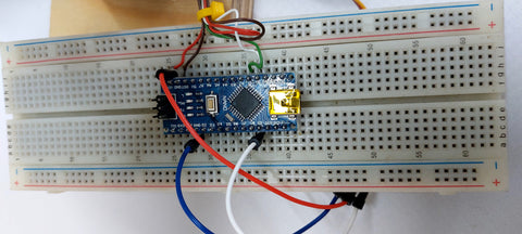
First start by connecting the stepper motor to your Arduino. As the connectors on the sg90 Servo motors are all female connectors you'll be using the Male to Male jumper wires for connecting the servo to the bread board. There are 3 wires on the servo: Red(5V+), Brown(GND) and Yellow(Signal). Connect the Red wire to the 5V pin on the Arduino, Brown to GND and Yellow to D9. As the servo motors position is controlled using PWM there are only a few selected pins on the nano that has PWM capabilities. These pins are : D3, D5, D6, D9, D10, D11 as can be seen in the image below.
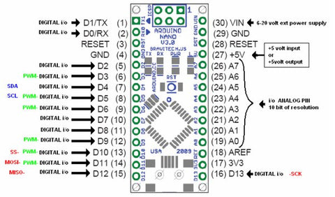
Arduino Nano V3 Pinout
Now that the servo motor is connected you'll need to add the LDR's. Start by connecting one leg of each LDR to 5V and each of the remaining legs to 10k Resistors connected to GND. You'll need to stick an LDR on each side of your solar panel.
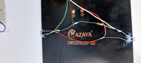
Lastly connect a wire from each leg between the resistor and the LDR for reading the voltage differential to any two analog pins, for this example we will be using A0 and A1.
Now that were done with the circuit we will be moving on to the software implementation of the project.
Software
First start off by connecting your mini Nano USB cable to the Arduino and plugging it into your PC. We'll be using the Arduino IDE to upload the Sketch to your Arduino.
Here is the code we'll be working with :
#include <Servo.h> //Library for controlling the position of the servo

Servo servo ;

int eastLDR = 0;//Analog pin A0
int westLDR = 1;//Analog pin A1
int LDR1 = 0;//LDR at the east side of the solar panel
int LDR2 = 0;//LDR at the west side of the solar panel
int error = 0;
int calibration1 = 0;//Only change if you are using 2 different types of LDR's and want to calibrate manually
int calibration2 = 0;//Only change if you are using 2 different types of LDR's and want to calibrate manually
int servoposition = 90;//Solar panel should face straight up when servo position is 90
void setup()

{
  servo.attach(9);//Attach the servo to the PWM pin for position control.
}

void loop()
{
  LDR1 = calibration1 + analogRead(eastLDR);//Reads the analog value of the LDR and adjusts accordingly with the calibration value selected.
  LDR2 = calibration2 + analogRead(westLDR);
  if (LDR1 < 350 && LDR2 < 350)
  {
    while (servoposition <= 150)
    {
      servoposition++;
      servo.write(servoposition);
      delay(100);
    }
  }
  error = LDR1 - LDR2;//Calculates the difference between the LDR readings, you can change the error range if the device is too sensitive.
  if (error > 15)
  {
    if (servoposition <= 150)
    {
      servoposition++;
      servo.write(servoposition);
    }
  }
  else if (error < -15)
  {
    if (servoposition > 20)
    {
      servoposition--;
      servo.write(servoposition);
    }
  }
  delay(100);
}
How does this code work?
First start off by adding the necessary libraries and declaring all the variables to be used, also the servo uses the attach function declaring which pin will be used as the PWM signal:
#include <Servo.h> //Library for controlling the position of the servo

Servo servo ;

int eastLDR = 0;//Analog pin A0
int westLDR = 1;//Analog pin A1
int LDR1 = 0;//LDR at the east side of the solar panel
int LDR2 = 0;//LDR at the west side of the solar panel
int error = 0;
int calibration1 = 0;//Only change if you are using 2 different types of LDR's and want to calibrate manually
int calibration2 = 0;//Only change if you are using 2 different types of LDR's and want to calibrate manually
int servoposition = 90;//Solar panel should face straight up when servo position is 90
void setup()

{
  servo.attach(9);//Attach the servo to the PWM pin for position control.
}
Next the calibration takes place, if the LDR sensors are the same type no calibration value is needed. In the first IF statement the program checks if both LDR's have low light readings, If so, adjust the position of the panel to a more optimal light source.
 LDR1 = calibration1 + analogRead(eastLDR);//Reads the analog value of the LDR and adjusts accordingly with the calibration value selected.
  LDR2 = calibration2 + analogRead(westLDR);
  if (LDR1 < 350 && LDR2 < 350)
  {
    while (servoposition <= 150)
    {
      servoposition++;
      servo.write(servoposition);
      delay(100);
    }
  }
After the solar panel has been adjusted to a position with adequate sunlight on both LDR sensors the position will be fine tuned with an error calculated by subtracting the LDR readings from each other. If the error is greater than 15 the solar panel moves East, If the error is less than -15 the solar panel moves West. At the end of the code there is a delay which translates directly to response time of the solar panel
 error = LDR1 - LDR2;//Calculates the difference between the LDR readings, you can change the error range if the device is too sensitive.
  if (error > 15)
  {
    if (servoposition <= 150)
    {
      servoposition++;
      servo.write(servoposition);
    }
  }
  else if (error < -15)
  {
    if (servoposition > 20)
    {
      servoposition--;
      servo.write(servoposition);
    }
  }
  delay(100);
Thanks for following along!!
This is the final project after completing all the steps:
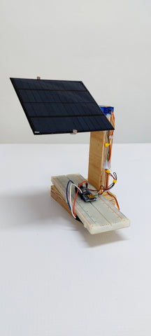
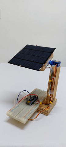
Sun following solar panel