The MOSFET (Metal Oxide Semiconductor Field Effect Transistor) transistor is a semiconductor device that is widely used for switching purposes and for the amplification of electronic signals in electronic devices. A MOSFET is either a core or integrated circuit where it is designed and fabricated in a single chip because the device is available in very small sizes. The introduction of the MOSFET device has brought a change in the domain of switching in electronics. Let us go with a detailed explanation of this concept.
What components will you need for this project?
For this project to work properly we will need a few components which can all be purchased from our website. Although I do recommend buying a few extra components as you might blow something if this is your first time prototyping.
- IRL2505 MOSFET X6
- 10k Resistor(Pack of 10) X1
- 1k Resistor(Pack of 10) X1
- Vero prototyping board X1
- Optocoupler X1
- Soldering Iron X1
- Solder X1
With these components you are ready to get started !
Multiple Mosfets in Parallel?
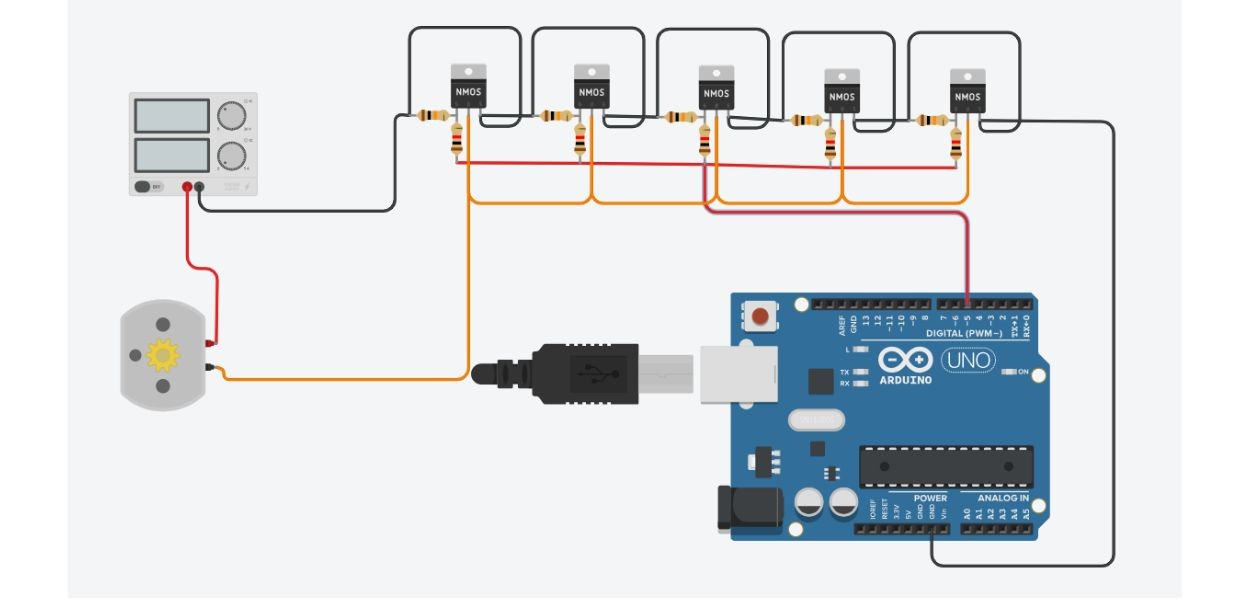
In certain cases, relying on a single MOSFET (Metal-Oxide-Semiconductor Field-Effect Transistor) might not provide the desired level of performance or handle the required electrical load effectively. To address this limitation, we can employ a technique known as "parallel MOSFET connection." This involves connecting multiple MOSFETs together in parallel configuration, effectively combining their capabilities. By doing so, we can enhance the overall power handling capacity, reduce heat generation, and improve the efficiency of the electrical circuit. This technique is particularly useful when dealing with high-power applications, where a single MOSFET may not be sufficient to meet the demands placed upon it. We can add PWM to it to control the speed of high amp DC motors.
Why do we use the IRL2505 Specifically?
In certain situations, using logic-level MOSFETs is a common choice. Logic-level MOSFETs are a specific type of MOSFET designed to be triggered by low-voltage signals, typically operating at voltages compatible with devices like microcontrollers such as the Arduino. To control these MOSFETs with an Arduino, you can simply connect the Arduino's output pins to the MOSFET's gate terminal. By programming the Arduino to send a digital signal (high or low) to the gate, you can effectively control the MOSFET's switching action. This allows you to manage power flow or perform various tasks such as switching lights, motors, or other electronic components with ease, all while ensuring compatibility with the logic levels of the microcontroller. When combined with the parallel MOSFET setup, this approach can provide both the necessary power handling capacity and precise control, making it a versatile solution for a wide range of electronic applications. We will be using 6 MOSFET's for our design, but you can add as many as you'd like !
What can our board handle?
There are many factors that affect the capacity of our board. These factors include, but are not limited to :
- How far our mosfets are spaced from each other. (Further spacing will improve ventilation, lowering the heat and reducing the resistance, meaning we can pull more current from our board)
- What type of MOSFETS are used. ( Each MOSFET has a maximum AMP rating which will give you a good idea of what voltage and amperage it can handle)
- How good our boards mounting and soldering is. ( Larger contact surfaces dissipates more heat and pulls more amps.)
- What duration of time it will be used for ( Longer durations require more heat dissipation)
- Do we have heat sinks? ( Adding heat sinks can increase the maximum amp rating of our MOSFETS by adding additional heat dissipation.)
But for a general thumb suck rule we can add 20 amps to our circuit for each IRL2505 MOSFET we connect.
Let's have a look at the IRL2505
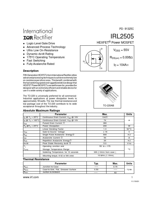
The IRL2505 is a logic-level MOSFET designed for switching applications that can operate with a gate voltage of 5V. This MOSFET is commonly used in various electronic circuits and devices. It has several key features and specifications, including:
1) MOSFET Type: N-channel MOSFET.
2) Package Type: TO-220AB package.
3) Maximum Continuous Drain Current (ID):
4) 104A at 25°C with VGS (Gate-to-Source Voltage) at 10V.
5) 74A at 100°C with VGS at 10V.
6) Pulsed Drain Current (IDM): 360A.
7) Power Dissipation (PD): 200W at 25°C.
8) Gate-to-Source Voltage (VGS): ±16V.
9) Avalanche Energy (EAS): 500mJ.
10) Avalanche Current (IAR): 54A.
11) Repetitive Avalanche Energy (EAR): 20mJ.
12) Diode Recovery dv/dt: Up to 5.0 V/ns.
13) Operating Temperature Range: -55°C to +175°C.
14) Gate Drive Compatibility: Logic-level MOSFET, making it suitable for use with low-voltage control signals, like those from microcontrollers or logic devices.
The IRL2505 is commonly used in various electronic applications where the efficient switching of high currents is required, and it can be driven by logic-level signals, such as those provided by microcontrollers like Arduino. This MOSFET is particularly well-suited for applications that demand high power handling and precise control. This makes it IDEAL for our project.
Key Terminals: Gate, Source, and Drain
To understand parallel MOSFET configurations, it is important that you grasp the function of the three essential terminals on a MOSFET:
Gate (G): The gate terminal is like the gatekeeper of the MOSFET. It regulates the flow of current between the source and drain. In your circuit, a 1kΩ gate resistor is connected from your Arduino input to the gate. When a voltage is applied to the gate terminal, and it surpasses a specific threshold voltage (typically between 2-4 volts for standard logic-level MOSFETs), the MOSFET turns on. This allows current to flow from the source to the drain. Conversely, when the gate voltage is below this threshold, the MOSFET turns off.
Source (S): The source terminal is where the current originates, and it is typically connected to the ground reference in your circuit. Here, a pull-down resistor is linked to the source. The purpose of the pull-down resistor is to ensure that when the gate isn't actively driven high (i.e., when it's in a high-impedance state or set to LOW), the gate voltage is effectively pulled down to ground (0V). This maintains the MOSFET in the off state, preventing unintended switching when the Arduino's gate output is not actively driving it.
Drain (D): The drain terminal is where the current exits the MOSFET and enters the load, which could be a motor, light bulb, or any other electrical component. When the MOSFET is turned on, typically through a voltage applied to the gate, current can flow from the source to the drain. In your circuit with parallel MOSFETs, this terminal connects to your load, allowing the distribution of load current evenly among the MOSFETs.
Now lets get to wiring of this board.
The Pull-Down Resistor(10K): Maintaining Control and Avoiding Floating Voltages
The pull-down resistor is a critical element in your MOSFET circuit. It is connected between the gate terminal and ground (0V). But what purpose does it serve, and why is it indispensable?
Preventing Floating Voltages:
When the gate of a MOSFET is left unconnected or in a high-impedance state, it can be susceptible to floating voltages. These voltages, induced by electromagnetic interference or other external factors, can lead to unexpected and unwanted MOSFET switching, causing malfunctions in your circuit. The pull-down resistor provides a stable path to ground when the gate isn't actively being driven high, effectively anchoring the gate terminal to a known and stable voltage level (0V).
Ensuring MOSFET Turn-Off:
MOSFETs require a minimum voltage level on the gate to turn on. If the gate voltage is below this threshold, the MOSFET stays off. The pull-down resistor keeps the gate at a potential of 0V, ensuring that the MOSFET remains in the off state when it's not actively being controlled by your Arduino or another source.
The Gate Resistor:
Smooth Transition and Reduced Current Surge
The gate resistor is another integral component in your circuit, particularly when dealing with microcontrollers like an Arduino. This resistor is connected between your Arduino's output pin and the gate terminal of the MOSFET.
Current Limitation:
The gate resistor acts as a current limiter. When the microcontroller pin transitions from low to high or vice versa, it can generate a brief surge of current, potentially causing stress on both the microcontroller pin and the MOSFET. The gate resistor moderates this current, preventing abrupt spikes that could damage the gate.
Signal Conditioning:
Additionally, the gate resistor can help to smooth out transitions between logic states. This can reduce the likelihood of noise or interference inadvertently triggering the MOSFET.
From beginner to final product:
In summary, the pull-down resistor keeps the gate voltage stable and grounded when it's not actively driven high, ensuring the MOSFET stays off and avoiding unwanted switching. The gate resistor serves to limit the current flow during transitions and provides signal conditioning for smoother and more reliable operation, especially when interfacing with microcontrollers.
Understanding these two resistors' roles in your MOSFET circuit not only safeguards the integrity of your components but also illustrates the meticulous design considerations essential for creating reliable and efficient electronic systems. As you embark on your electronic projects, remember that every component, no matter how seemingly insignificant, plays a vital part in the overall functionality of your circuit.
Here is an example of the circuit I built using the information provided above:
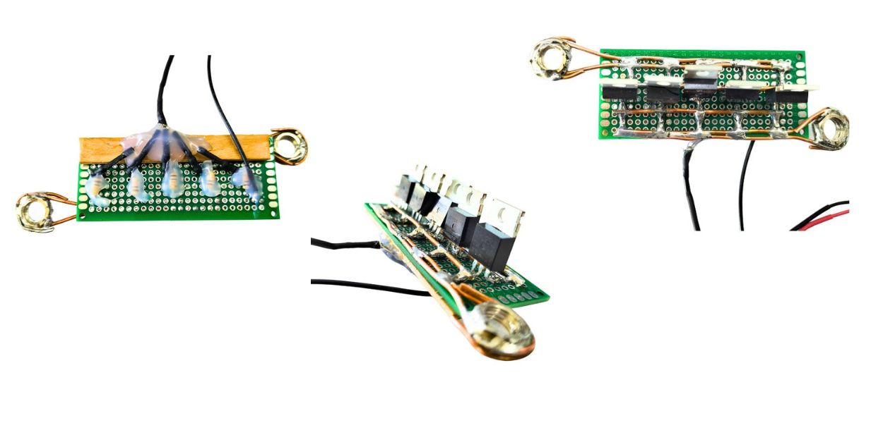
As can be seen in the image provided above I used a glue gun to keep my wires in place and used thick copper wires to carry as much amps as possible. Although it does look a bit rough around the edges it works perfectly. I used nuts for the connection holes which I soldered to the rail although I do recommend using lugs as an easier and neater alternative. I also added an optocoupler for the board to switch below 5v (Using an esp32 with 3.3v logic).
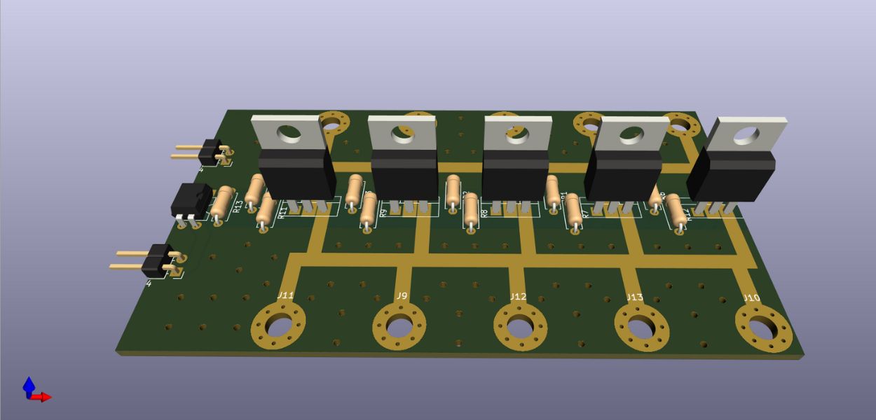
Something to look forward to:
If you are not in the mood for wiring everything and struggling with a vero board you can always be on the lookout for our new MOSFET Rail board which will be released soon. I will link the product in this post once it's available.
HIGH CURRENT LOGIC LEVEL MOSFET SWITCH