555 PWM controller Project
Difficulty rating: Beginner
Average time to build: 30 minutes
The 555 IC is probably the most useful IC to play with when you learn about electronics.
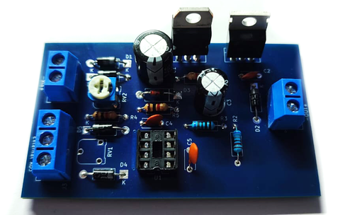
Short description
This DIY kit will help with your soldering skills, while you learn about the standard 555 timer IC.
The kit teaches you how the IC uses PWM as a way to control the power of a load.
It intergrades a voltage-follower NPN transistor and Zenner as a stable voltage regulator.
So, you have a constant power source to the IC that will then make our control more stable.
Using PWM to control our DC motor speed or dimming a 20W car lamp, easily with this PCB.
555 PWM Project building summary
In this project, you will need the kit as well as a soldering iron, solder and pliers to cut the legs of the components shorter once completed.
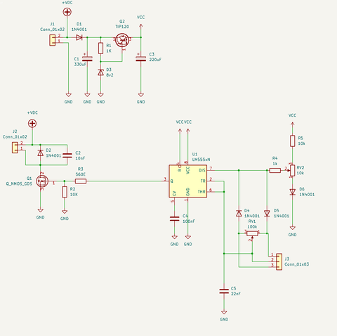
Project Diagram
How the 555 PWM controller works
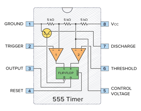
For more on this click on the link: How to Generate PWM using 555 Timer IC? 555 Timer PWM Circuit (electronicshub.org)
Step-by-step instructions.
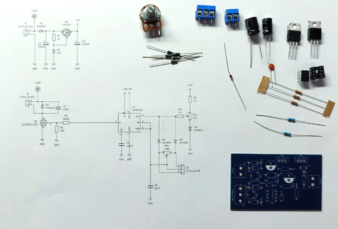
The picture above shows all the components that come with the kit.
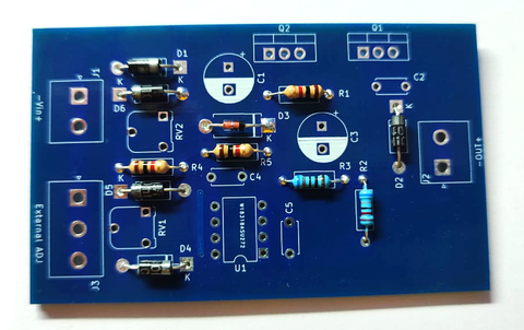
Step1
Place all Resistors, Diode, Zenner and solder pins (always start with the lowest components, this will make soldering easy when flipping the PCB when soldering bottom.)
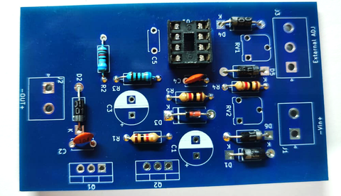
Step2.
Place IC holder, ceramic Cap and solder pins (these are the next higher components.)
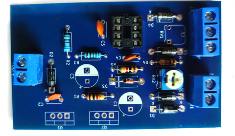
Step 3.
Place 10k pot and 2Pin with 3Pin connector and solder pins(this will be the next highest components.)

Step 4
Place Electrolytic Capacitors and make sure of polarity they do have +,- pins neg are marked with white marking on the side and short wire pin, and last place the Tip120 NPN transistor with a metal case to the back as seen in the picture and Mosfet next to it and solder pins.
Step5
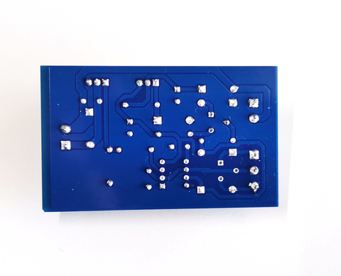
Finally, we can inspect the board for any shorts or missing soldering pins.
If all looks good we can power the board and we will test the dimming control.
555 PWM controller Kit