555 Flip Flop Project
The kit teaches you how the 555 IC can flash 2 LEDs, one ON and one Off at 50% interval.
Difficulty rating: Beginner
Average time to build: 30 minutes.
The 555 IC is probably the most useful IC to play with when you learn about electronics.
Short description
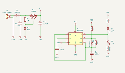
It intergrades a voltage-follower NPN transistor an Zenner as a stable voltage regulator.
So you can power it with 8-15V and no need to worry about the flashing rate varying between on-off times of the LEDs.
This is a great project to make two LED's flash one after the other without needing a microcontroller.
555 Flip Flop Project building summary
In this project you will need the kit as well as a soldering iron, solder and pliers to cut the legs of the components shorter once completed.
Project diagram
How the 555 timer works
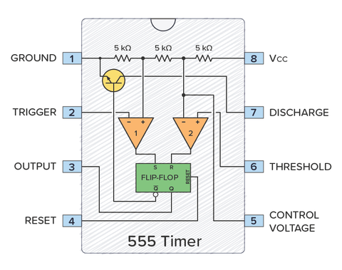
At the top of the diagram above, you have three 5 kΩ transistors between VCC and GND.
These resistors divide the VCC voltage in three.
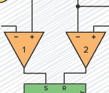
Below the resistors, there are two triangles. These are comparators. If the comparator input marked with + has a higher voltage than the one marked with −, the output is high; otherwise, the output is low.
Comparators inside the 555 Timer
The 5k resistors set fixed voltages for each of the comparators: one-third of the VCC voltage goes to the positive (+) input of comparator 1, and two-thirds of the VCC voltage goes to the negative (–) input of comparator 2.
The green box is an SR Flip-Flop. It is a simple memory device with two states: output high (flip) and output low (flop).
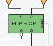
SR Flip-flop inside the 555 Timer
It has two inputs, set (S) and reset (R). S sets the output (Q) to high, and R resets it to low.
Q is always the opposite of Q.
Comparator 1 checks if the voltage on the Trigger pin is below 1/3 of VCC. If it is, it sets the flip-flop so that the Output pin becomes high.
Comparator 2 checks if the voltage on the Threshold pin is above 2/3 of VCC. If it is, it resets the flip-flop so that the Output pin becomes low.
The flip-flop also controls a transistor that connects the Discharge pin to ground when the output is low.
![]()
Transistor inside 555 timers
Summary
The pins responsible for making the Output (pin 3) go high or low are the Trigger (pin 2) and the Threshold (pin 6).
The Trigger pin is responsible for setting the output high. When the voltage on the trigger pin goes lower than one-third of VCC, comparator 1 outputs high and sets the flip-flop high, which in turn sets the Output pin high.
Pin 6 is labeled Threshold; when its voltage exceeds two-thirds of the VCC, it is responsible for resetting the Output back to low.
Link to product bundle with price e.g. Sound to light components - R380.00
Step by step instructions.
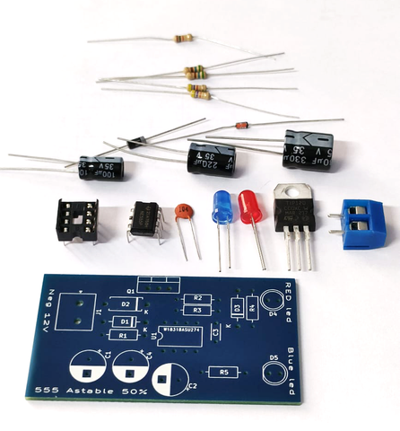
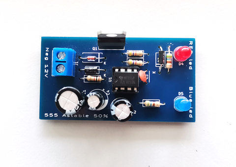
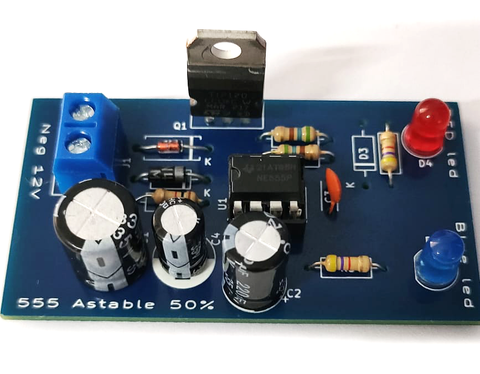
The picture above shows all the components that comes with the kit.
Step1
Place all Resistors, Diode, Zenner and solder pins (always start with the lowest devices, will make soldering easy when flipping pcb when soldering bottom.)
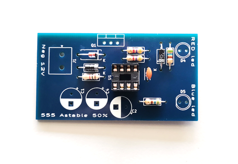
Step2.
Place IC holder, ceramic Cap and solder pins (this are the next higher devices.)
Step 3.
Place LED's make sure of polarity LEDs do have +, - pins neg are mark with flat edge and short wire pin, add 2Pin connector and solder pins (this will be the next highest devices.)
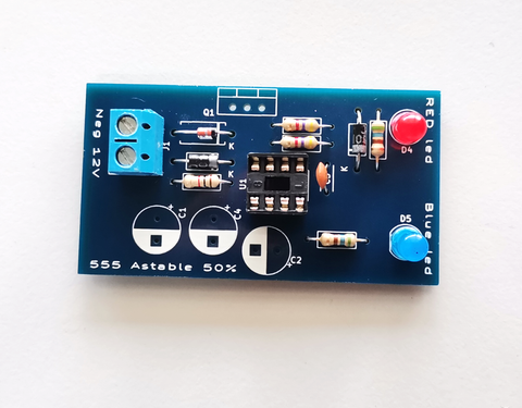
Step 4
Place Electrolytic Capacitors and make sure of polarity they do have +, - pins neg are marked with white marking on the side and short wire pin, and last, place the Tip120 NPN transistor with a metal case to the back as seen in the picture and solder pins.
Step5
Now finaly we can inspect the board for any shorts or miss soldering pins.
If all looks good we can power the board and we will see led's flashing.
555 Flip Flop Project