Adjustable step-up step-down buck boost converter
As mentioned in the description a buck-boost converter board will keep a pre-set voltage even if the voltage is below (step-up) or above (step down) the pre-set value. It works especially great where the power source fluctuates a lot e.g. solar panels.
This is called a Cuk converter a type of DC/DC converter that has an output voltage magnitude that is either greater than or less than the input voltage magnitude. It is essentially a boost converter followed by a buck converter with a capacitor to couple the energy.
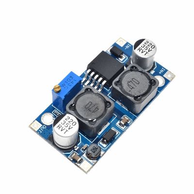
Please note that the trim pot that is used to adjust the output of the module needs to be turned quite a few times before you can see a change in the output.
Buck boost converter specifications
Rated at 1A, 3A for short periods with heatsink

In the non-isolated Cuk converter, the input and output circuits share the common ground. The non-isolated Cuk converter topology consists of DC input voltage source Vin, input inductor L1, one controllable switch S, energy transfer capacitor C1, diode D, filter inductor L2, filter capacitor C2, and load resistance R. This converter exchanges energy between the inductor L1, capacitor C1, and inductor L2 to convert input DC voltage to required output voltage level. A power transistor switch (S1) such as a MOSFET is used to control the amount of energy exchanged.