Water Flow Controller project
Difficulty rating: Advanced
Average time to build: 45 minutes.
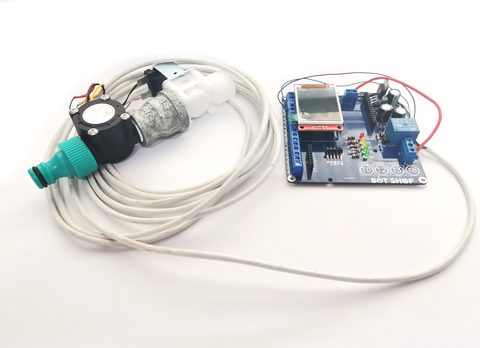
Quick description
With this project, you can control the total volume of liquid that you add to a vat, for instance adding water to your dough mix in a bakery. Using the touch buttons on the Project board you can adjust the amount of liquid in increments of 100ml.
this makes it easy to measure out liquids for everyday use, which means no more measuring jugs.
Water Flow Controller building summary.
To be able to build this project all you need is a flow meter, a solenoid valve, and our Project Board.
The flow sensor contains a hall effect sensor and a magnet that is mounted on a spinning turbine. When a magnet comes close to a hall effect sensor the hall effect sensor will give out a digital signal. This signal we can then pick up on a microcontroller. By counting the number of times, the magnet passes by the hall effect sensor we can calculate the volume of liquid that has passed through the sensor.
Step-by-step instructions.
Step 1.
Assemble the flow meter and solenoid valve like in the image below, keep in mind that the flow meter should be before the solenoid valve to avoid the turbine from spinning freely after shutting the solenoid valve down. Pay attention to the arrows on the meter and valve, the arrows point in the direction in which the water will flow. When it comes to wiring the meter and valve you can use any wire that you have available. I used a normal alarm comms cable.
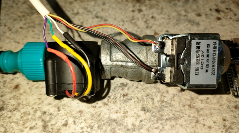
Step 2
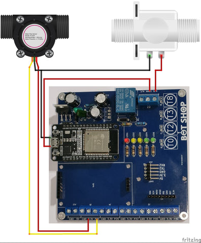
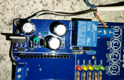
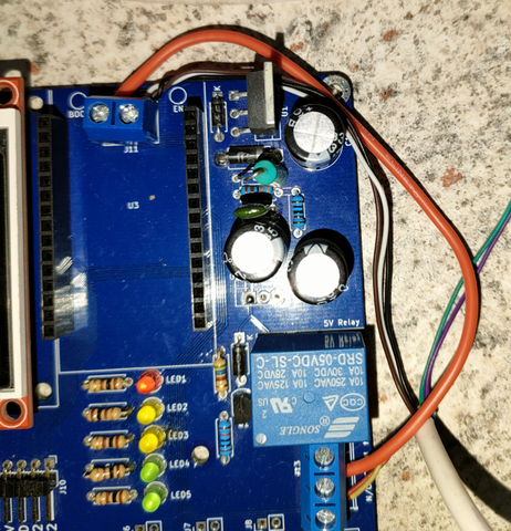
Connect one end of your solenoid valve to the N/O Pin of the relay and connect the other end of the solenoid valve along with the negative of the flow meter to the negative of your input supply.
Step 3
Add a jumper between the positive of the input voltage and the COMM Pin of the relay. This jumper will supply a voltage to the solenoid once the relay is switched.
Step 4
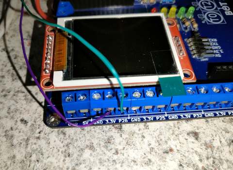
Connect the data wire (Yellow) of the Flow sensor to P26 of the project board and the VCC wire (Red) to 3.3V. When you are using different color wires as we did here pay close attention so that you do not swap the wires around. In the image below I used a purple wire for VCC and green for data.
Step 5
Plug in your ESP32 and your screen to its respective slots and upload your code.
Extra notes
- If it is the first time you run this code or you want to return the unit to factory settings, there is a factory reset function built into the code to clear the EEPROM and enter usable values into the EEPROM. To do this just hold in T2 during startup and follow the on-screen prompts.
- The button functions are.
- T0 - Start
- T2 - Stop
- T3 - Decrease with 100ml.
- T4 - Increase with 100ml
- There is a bonus button programmed into the code for pulsing the valve, to use this button connect a push button between GND and P25.
- Before operating the controller make sure that you remove all air bubbles from your fluid line by running the controller a few times. Water bubbles in your fluid line can cause inaccurate values.
- Make sure that you put the valve as close to the end as possible to prevent water from getting trapped in the put instead of in your container.
Code example
