ESP32 & LoRa Transceiver.
Welcome, fellow tech enthusiasts! Today, we're embarking on an exciting journey into the world of DIY electronics with the ESP32 & LoRa Transceiver project! In this project, we'll be wirelessly transmitting temperature and humidity data using the power of the ESP32 and LoRa. But that's not all. Throughout this project, we'll be learning how to use ESPs, LoRas, DHT11s, and an OLED 0.96 display, while also flexing our coding muscles in the Arduino IDE. So, grab your soldering iron, put on your thinking caps, and let's dive into the wonderful world of IoT with this fun and customizable project!
This is my first Arduino project?
If this is your first Arduino project or you need a little more insight on the components you're working with, here are a few useful links to get you started :
- Downloading and getting started with Arduino IDE
- What are Libraries?
- How to add Libraries to Arduino IDE
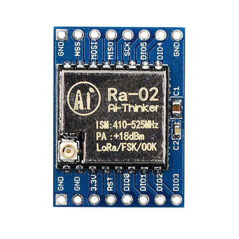
- All about LoRa
- All about ESP32
- How to program ESP32 with Arduino
- OLED 0.96 LCD
Software requirements.
For this project you'll need to add the DHT11 library, LoRa library, OLED 0.96 library in your Arduino IDE. Simply go to Sketch>Include Library> Manage Libraries. When the window opens search for the ''DHT11, LoRa, and OLED'' library and install the first one that pops up.
- Arduino IDE
- SPI.h Library
- LoRa.h Library
- DHT.h Library
- Wire.h Library
- Adafruit_SSD1306.h Library
Hardware requirements
There are a few components needed for this project to work which I will add links to :
The hardware in the list above can all be bought from our website.
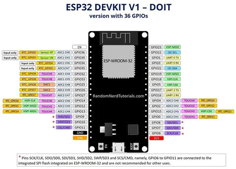
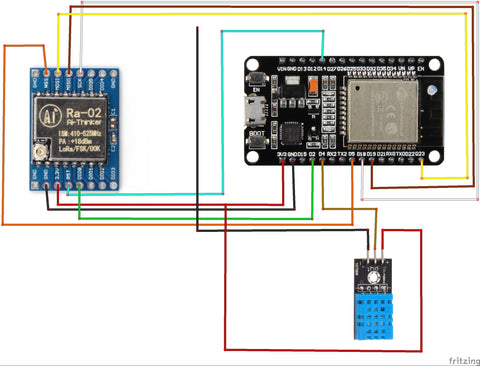
Circuit diagram
First we need to start by connecting the LoRa and the ESP32 to each other as follows below :
LoRa | ESP32 |
GND | GND |
3.3V | 3.3V |
DI0 | GPIO 2 |
RESET | GPIO 14 |
NSS | GPIO 5 |
SCK | GPIO 18 |
MOSI | GPIO 23 |
MISO | GPIO 19 |
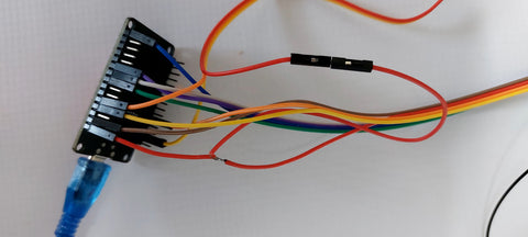
So, now that the ESP32 and LoRa is connected we need to connect the DHT11 for us to be able to get the temperature and humidity data that we require. To connect the DHT11 you can strip the wire that connects the LoRa module to the 3.3V pin on the ESP32 in the middle. Next, you can take a male-to-female wire and connect it to the stripped part of the wire. Finally, you can connect the female end of the wire to the DHT11 sensor to provide it with 3.3V power. This part will require soldering.
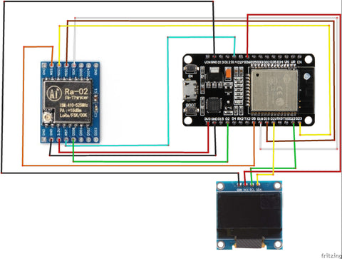
Now we're going to connect a small screen onto the project as this will allow us to view the Temperature and Humidity with out the assistance of a serial monitor. So to connect the screen we need to understand how this will work and why it works. The ESP32 can give us 3.3V on any of its GPIO pins as long as we set the pinout in our Code to give us an output of 3.3V.
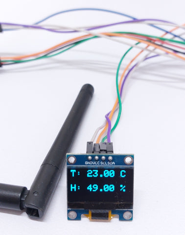
The connection of the screen is very simple and easy to do. First we need to connect it to VCC and GND then we need to connect the SCL and SDA to specific pins on the ESP32. So VCC can be connected to any of our GPIO pins, for this project we selected GPIO pin 26, the ESP32 has multiple GND pins so we can just connect the GND to one of the ESP32s GND pins, then we connect the SCL pin of the OLED screen to GPIO pin 22 and the SDA pin of the screen to GPIO pin 21, please note that the SCL and the SDA pins have specific pins they connect to on the ESP32 and they must be connected correctly other wise the screen will not display our data.
Circuit diagram Sender
Circuit diagram Receiver
Coding the ESP32&LoRa Sender
When it comes to coding the modules it can be quite hard but I have already coded the basic structure. You can copy the code and change it as you like. Also feel free to share any improvements and ideas.
This is the code for the Sender:
#include <SPI.h>
#include <LoRa.h>
#include <DHT.h>

//define the pins used by the transceiver module
#define ss 5
#define rst 14
#define dio0 2

//define the pins used by the DHT11 sensor
#define DHTPIN 4
#define DHTTYPE DHT11

int counter = 0;

//initialize DHT11 sensor
DHT dht(DHTPIN, DHTTYPE);

void setup() {
  //initialize Serial Monitor
  Serial.begin(115200);
  while (!Serial);
  Serial.println("LoRa Sender");

  //initialize DHT11 sensor
  dht.begin();

  //setup LoRa transceiver module
  LoRa.setPins(ss, rst, dio0);

  //replace the LoRa.begin(---E-) argument with your location's frequency
  //433E6 for Asia
  //866E6 for Europe
  //915E6 for North America
  while (!LoRa.begin(433E6)) {
    Serial.println(".");
    delay(500);
  }
   // Change sync word (0xF3) to match the receiver
  // The sync word assures you don't get LoRa messages from other LoRa transceivers
  // ranges from 0-0xFF
  LoRa.setSyncWord(0xF3);
  Serial.println("LoRa Initializing OK!");
}

void loop() {
  //read temperature and humidity data from DHT11 sensor
  float h = dht.readHumidity();
  float t = dht.readTemperature();

  //check if reading DHT11 sensor was successful
  if (isnan(h) || isnan(t)) {
    Serial.println("Failed to read from DHT sensor!");
    return;
  }

  Serial.print("Sending packet: ");
  Serial.print(counter);
  Serial.print(", Temperature: ");
  Serial.print(t);
  Serial.print(", Humidity: ");
  Serial.println(h);

  //Send LoRa packet to receiver
  LoRa.beginPacket();
  //LoRa.print("Temperature: ");
  LoRa.print(t);
  LoRa.print(",");
  LoRa.print(h);
//  LoRa.print(" Humidity: ");
//  LoRa.print(h);
  LoRa.endPacket();

  counter++;

  delay(50);
}
How does this code work?
First off start by adding the necessary libraries and declaring the pins for the LoRa and also the DHT11. Also we will need to declare a counter, that will allow you to see the amount of packages that were sent between the 2 LoRas, we are not displaying this data on the screen but it can be viewed on the serial monitor in the Arduino IDE.
#include <SPI.h>
#include <LoRa.h>
#include <DHT.h>

//define the pins used by the transceiver module
#define ss 5
#define rst 14
#define dio0 2

//define the pins used by the DHT11 sensor
#define DHTPIN 4
#define DHTTYPE DHT11

int counter = 0;
The code block below initializes the Serial Monitor for communication and checks that it's connected before printing "LoRa Sender" on it. It also sets up a DHT11 sensor using the "dht.begin()" function, preparing it to collect temperature and humidity data. This code block sets up the environment for sending data using LoRa while also initializing the necessary tools for measuring the environment.
void setup() {
  //initialize Serial Monitor
  Serial.begin(115200);
  while (!Serial);
  Serial.println("LoRa Sender");

  //initialize DHT11 sensor
  dht.begin();
The code block below sets up the pins for communicating with a LoRa transceiver using the "LoRa.setPins()" function. Then, it uses the "LoRa.begin()" function to start communication at a specific frequency. The frequency depends on where you are in the world but for this project, we are using the 433E6 frequency. The while loop checks that the LoRa has successfully begun communication, and prints "." on the Serial Monitor while it waits. After successful initialization, the code sets the sync word (This is basically a password 0xF3) to match the receiver, ensuring that messages are only received from the intended source. Finally, it prints "LoRa Initializing OK!" to signal that everything is ready to go.
 //setup LoRa transceiver module
  LoRa.setPins(ss, rst, dio0);

  //replace the LoRa.begin(---E-) argument with your location's frequency
  //433E6 for Asia
  //866E6 for Europe
  //915E6 for North America
  while (!LoRa.begin(433E6)) {
    Serial.println(".");
    delay(500);
  }
   // Change sync word (0xF3) to match the receiver
  // The sync word assures you don't get LoRa messages from other LoRa transceivers
  // ranges from 0-0xFF
  LoRa.setSyncWord(0xF3);
  Serial.println("LoRa Initializing OK!");
}
The code block below is part of the loop that runs repeatedly. It reads temperature and humidity data from the DHT11 sensor using two float variables, "h" and "t"(Humidity and Temperature). The code checks if the sensor reading was successful using an "if" statement. If either the humidity or temperature reading is "not a number" (NaN), it should print "Failed to read from DHT sensor!" on the Serial Monitor and ends the loop using "return". This helps to prevent errors caused by incomplete or inaccurate sensor readings. If the readings are valid, the loop continues to the next block of code.
 void loop() {
  //read temperature and humidity data from DHT11 sensor
  float h = dht.readHumidity();
  float t = dht.readTemperature();

  //check if reading DHT11 sensor was successful
  if (isnan(h) || isnan(t)) {
    Serial.println("Failed to read from DHT sensor!");
    return;
  }
The code block below prints a message on the Serial Monitor that shows the packet number, temperature, and humidity readings from the DHT11 sensor. It then sends the packet to the LoRa receiver using "LoRa.beginPacket()" and "LoRa.endPacket()". The temperature and humidity readings are included in the packet using "LoRa.print()", with a comma separating the two values. The "counter" variable is incremented to keep track of the number of packets sent. Finally, the code pauses using a "delay(50)" This delay is incremented in milliseconds so the code waits for 50 milliseconds before looping back to the beginning of the code.
 Serial.print("Sending packet: ");
  Serial.print(counter);
  Serial.print(", Temperature: ");
  Serial.print(t);
  Serial.print(", Humidity: ");
  Serial.println(h);

  //Send LoRa packet to receiver
  LoRa.beginPacket();
  //LoRa.print("Temperature: ");
  LoRa.print(t);
  LoRa.print(",");
  LoRa.print(h);
//  LoRa.print(" Humidity: ");
//  LoRa.print(h);
  LoRa.endPacket();

  counter++;

  delay(50);
}
Now just hit upload and the code should work fine. As we are done with the sender, next we will do the receiver:
Coding the ESP32&LoRa receiver
So the receiver is quite simple as it just receives the data and prints it out on the i2c display. Here is the code we'll be working with :
//Include the necessary libraries
#include <Wire.h>
#include <SPI.h>
#include <LoRa.h>
#include <Adafruit_SSD1306.h>
#include <Adafruit_GFX.h>

#define SCREEN_WIDTH 128
#define SCREEN_HEIGHT 64
Adafruit_SSD1306 display(SCREEN_WIDTH,SCREEN_HEIGHT,&Wire);
String temp;
String hum;

//define the pins used by the transceiver module
#define ss 5
#define rst 14
#define dio0 2

int counter = 0;

void setup() {
  pinMode(26,OUTPUT);
  delay(100);
  digitalWrite(26,HIGH);
  delay(100);
  //initialize Serial Monitor
  Serial.begin(115200);
  while (!Serial);
  Serial.println("LoRa Receiver");

  display.begin(SSD1306_SWITCHCAPVCC, 0x3C);
  display.display();
  delay(2000);
  display.clearDisplay();

  //setup LoRa transceiver module
  LoRa.setPins(ss, rst, dio0);

  //replace the LoRa.begin(---E-) argument with your location's frequency
  //433E6 for Asia
  //866E6 for Europe
  //915E6 for North America
  while (!LoRa.begin(433E6)) {
    Serial.println(".");
    delay(500);
  }
   // Change sync word (0xF3) to match the receiver
  // The sync word assures you don't get LoRa messages from other LoRa transceivers
  // ranges from 0-0xFF
  LoRa.setSyncWord(0xF3);
  Serial.println("LoRa Initializing OK!");
}

void loop() {
   digitalWrite(26,HIGH);
  // try to parse packet
  int packetSize = LoRa.parsePacket();
  if (packetSize) {
    // received a packet
//    Serial.print("Received packet '");

    // read packet
    while (LoRa.available()) {
      String LoRaData = LoRa.readString();
//      Serial.print(LoRaData);
      temp = LoRaData.substring(0,5);
      Serial.println(temp);
      hum = LoRaData.substring(6,11);
      Serial.println(hum);
    }

    // print RSSI of packet
    //Serial.print("' with RSSI ");
    //Serial.println(LoRa.packetRssi());
  }

  display.clearDisplay();
  display.setTextSize(2);
  display.setTextColor(WHITE);
  display.setCursor(0,0);
  display.print("T: ");
  display.print(temp);
  display.println(" C");
  display.setCursor(0,32);
  display.print("H: ");
  display.print(hum);
  display.println(" %");
  display.display();
  delay(50);
}
First off start by adding the necessary libraries and declaring the pins for the LoRa and also the OLED LCD Screen. Please keep in mind that we don't require a Temperature and Humidity sensor on the receivers side as we already have one on the sender and that's all we need for this project to work.
#include <Wire.h>
#include <SPI.h>
#include <LoRa.h>
#include <Adafruit_SSD1306.h>
#include <Adafruit_GFX.h>

#define SCREEN_WIDTH 128
#define SCREEN_HEIGHT 64
Adafruit_SSD1306 display(SCREEN_WIDTH,SCREEN_HEIGHT,&Wire);
String temp;
String hum;

//define the pins used by the transceiver module
#define ss 5
#define rst 14
#define dio0 2

int counter = 0;
The code segment below initiates the setup for a device or system. It sets digital pin 26 to and output mode, this is required for the screen to switch on, the we add a delay of 100 milliseconds, and then set the output voltage of pin 26 to high. Additionally, it initializes the Serial Monitor, which is a useful tool for debugging and monitoring the device. The baud rate for the Serial Monitor is set to 115200. The "while" loop ensures that the Serial Monitor is properly initialized before proceeding, and the final line of code prints the message "LoRa Receiver" to the Serial Monitor, indicating that the device is ready to receive LoRa signals. This code is a crucial component of the initialization process and ensures that the device functions correctly.
void setup() {
  pinMode(26,OUTPUT);
  delay(100);
  digitalWrite(26,HIGH);
  delay(100);
  //initialize Serial Monitor
  Serial.begin(115200);
  while (!Serial);
  Serial.println("LoRa Receiver");
Firstly, the code below initializes our small OLED LCD display using the SSD1306_SWITCHCAPVCC protocol with an address of 0x3C. After initializing, it displays the contents on the screen using "display.display();" function and then waits for two seconds before clearing the display with "display.clearDisplay();" function.
Secondly, the code sets up the LoRa transceiver module with three specific pins: ss, rst, and dio0. This module is used for long-range communication and is essential in many IoT and smart device projects. By setting these specific pins, the LoRa module can communicate with the other LoRa device and transmit data over long distances. Overall, this code plays an important role in setting up and configuring the hardware required for our ESP32&LoRa project.
 display.begin(SSD1306_SWITCHCAPVCC, 0x3C);
  display.display();
  delay(2000);
  display.clearDisplay();

  //setup LoRa transceiver module
  LoRa.setPins(ss, rst, dio0);
The code block below initializes and sets up the LoRa transceiver module for communication in a specific frequency band. The frequency band is set using the "LoRa.begin()" function argument, which needs to be changed according to the location, if you remember the sender part of this project you should also remember that we use 433E6 as our frequency. The code also includes a loop to ensure that the LoRa module is successfully initialized, indicated by the "LoRa Initializing OK!" message in the serial monitor. The sync word is the same as with the sender. This code is important for establishing reliable long-range communication between LoRa transceivers, which is a common requirement for this project.
 //replace the LoRa.begin(---E-) argument with your location's frequency
  //433E6 for Asia
  //866E6 for Europe
  //915E6 for North America
  while (!LoRa.begin(433E6)) {
    Serial.println(".");
    delay(500);
  }
   // Change sync word (0xF3) to match the receiver
  // The sync word assures you don't get LoRa messages from other LoRa transceivers
  // ranges from 0-0xFF
  LoRa.setSyncWord(0xF3);
  Serial.println("LoRa Initializing OK!");
}
This code block is a part of the "loop" function. It begins by setting digital pin 26 to high. The code then tries to receive and parse incoming data packets using the LoRa transceiver module. If a packet is successfully received, the code reads and extracts the data from the packet. The data is then printed on the serial monitor for debugging purposes, the data will also be printed onto our OLED LCD display and you can view both at the same time. The extracted data includes temperature and humidity readings, which are read as strings using the "LoRa.readString()" function. The temperature and humidity values are then stored in separate variables for further processing.
 void loop() {
   digitalWrite(26,HIGH);
  // try to parse packet
  int packetSize = LoRa.parsePacket();
  if (packetSize) {
    // received a packet
//    Serial.print("Received packet '");

    // read packet
    while (LoRa.available()) {
      String LoRaData = LoRa.readString();
//      Serial.print(LoRaData);
      temp = LoRaData.substring(0,5);
      Serial.println(temp);
      hum = LoRaData.substring(6,11);
      Serial.println(hum);
    }

    // print RSSI of packet
    //Serial.print("' with RSSI ");
    //Serial.println(LoRa.packetRssi());
  }
The code block below is mainly for the screen such as its refresh rate, character size etc. The first line clears the display to make way for new content. The next few lines set the text size and color to white, and set the cursor position for the next print statements. The code then prints out the current temperature and humidity values, followed by the respective units. The display is then updated with the new content and a short delay is added before the loop repeats. This suggests that the code is likely running on a device that is monitoring temperature and humidity and displaying the values on a screen in real-time.
 display.clearDisplay();
  display.setTextSize(2);
  display.setTextColor(WHITE);
  display.setCursor(0,0);
  display.print("T: ");
  display.print(temp);
  display.println(" C");
  display.setCursor(0,32);
  display.print("H: ");
  display.print(hum);
  display.println(" %");
  display.display();
  delay(50);
}
And this will be the end of this block post which teaches you how to build this project. Your project should be working as explained in this block post, if for some reason it does not please be so kind as to double check the connections between the ESP32, LoRa, and the OLED( Refer to the circuit diagram).
ESP32 & LoRa Transciever